IEC Standard for Busbar Contact Resistance
Understanding the IEC Standard for Busbar Contact Resistance
The IEC standard for busbar contact resistance plays a vital role in ensuring electrical safety, performance, and longevity of electrical systems. In power distribution networks, busbars are essential components that carry large amounts of current. The integrity of busbar joints is critical because poor connections can cause overheating, voltage drops, and even fire hazards. The International Electrotechnical Commission (IEC) sets out standardized testing procedures and benchmarks to ensure that busbar contact resistance remains within safe and acceptable limits.

IEC standards are developed through international consensus and are used globally. For busbar contact resistance, these standards help ensure that electrical installations are efficient, safe, and reliable over time. This article explores the technical aspects, testing procedures, allowable limits, and real-world applications of the IEC standard for busbar contact resistance in simple, human-readable language.
What is Busbar Contact Resistance?
Busbar contact resistance is the resistance at the interface where two busbars or a busbar and connector meet. In theory, these contacts should offer negligible resistance. But in practice, factors like surface oxidation, mechanical pressure, alignment, and cleanliness can significantly affect resistance levels. Increased contact resistance leads to heat generation, energy loss, and equipment failure.
To maintain system efficiency and reduce energy losses, busbar joints must be designed, installed, and maintained to meet the specifications set by IEC standards for busbar contact resistance.
Know more about IEC Standard for Battery Energy Storage System
Relevant IEC Standards for Busbar Contact Resistance
Several IEC standards directly or indirectly address busbar contact resistance. The most commonly referenced ones include:
| IEC Standard | Title | Relevance |
|---|---|---|
| IEC 61439 | Low-voltage switchgear and controlgear assemblies | Provides test procedures and limits for resistance |
| IEC 60297 | Mechanical structures for electronic equipment | Includes busbar assembly standards |
| IEC 60947 | Low-voltage switchgear and controlgear | Mentions test methods for resistance in connections |
| IEC 61238-1 | Compression and mechanical connectors for power cables | Often used in conjunction with busbar joint evaluation |
The most comprehensive information regarding the testing and measurement of contact resistance in busbar systems is available in IEC 61439, which is the cornerstone standard for low-voltage electrical assemblies. It mandates performance verification, including measurement of contact resistance under specified test conditions.
Why the IEC Standard for Busbar Contact Resistance Matters
Contact resistance is not just an abstract parameter. It directly affects the thermal performance and safety of a power distribution system. Even a small increase in resistance can cause severe heating when large currents are involved.
For instance, a joint with just 100 micro-ohms of resistance carrying 1000A would dissipate:
P = I²R = (1000)² × 0.0001 = 100 watts of heat
Over time, this heat can degrade insulation, damage surrounding materials, and reduce the life expectancy of electrical equipment. This is why strict adherence to the IEC standard for busbar contact resistance is essential in design, installation, and maintenance.
Know more about IEC Standard for Busbar Sizing
Key Requirements in IEC 61439 for Busbar Contact Resistance
IEC 61439 requires verification of the design and performance of busbar systems, including:
- Measurement of temperature rise at rated current
- Verification of contact resistance through millivolt drop testing
- Mechanical integrity of connections to avoid loosening over time
- Verification under operating and short-circuit conditions
The standard does not prescribe a specific contact resistance value but focuses on temperature rise and voltage drop limits. However, many manufacturers aim for contact resistance values less than 50 micro-ohms at busbar joints to meet these criteria comfortably.
Temperature Rise Test as Proxy for Contact Resistance
Instead of direct resistance measurement, IEC 61439 recommends temperature rise tests as a more practical and reliable method to evaluate contact quality. A typical allowable limit is a temperature rise of not more than 70°C above ambient for copper conductors.
This test indirectly verifies that the contact resistance is low enough not to cause excessive heating. Infrared thermography is often used during these tests to identify hotspots at joints.
Know more about IEC Standard for Air Circuit Breaker
Factors Affecting Busbar Contact Resistance
Several practical factors influence busbar joint performance:
- Surface Finish: Oxidized or corroded surfaces increase resistance.
- Contact Pressure: Loose bolts or improper torque application leads to higher resistance.
- Alignment and Flatness: Misaligned busbars reduce contact area and increase resistance.
- Materials: Copper offers better conductivity than aluminum but is more expensive.
- Environmental Conditions: Moisture, dust, and chemical exposure degrade contact integrity.
Maintaining busbar contact resistance within acceptable limits requires strict quality control during manufacturing, precise installation practices, and regular maintenance inspections.
Recommended Values for Contact Resistance
Although IEC 61439 focuses on temperature rise, many industry experts and manufacturers provide empirical guidelines for contact resistance levels.
| Application | Recommended Max Contact Resistance |
|---|---|
| Copper Busbar Joint | ≤ 50 µΩ |
| Aluminum Busbar Joint | ≤ 100 µΩ |
| Copper to Aluminum Joint | ≤ 75 µΩ |
| High-current Special Designs | ≤ 30 µΩ |
These values ensure efficient performance under typical operating currents in low-voltage systems.
How to Measure Busbar Contact Resistance
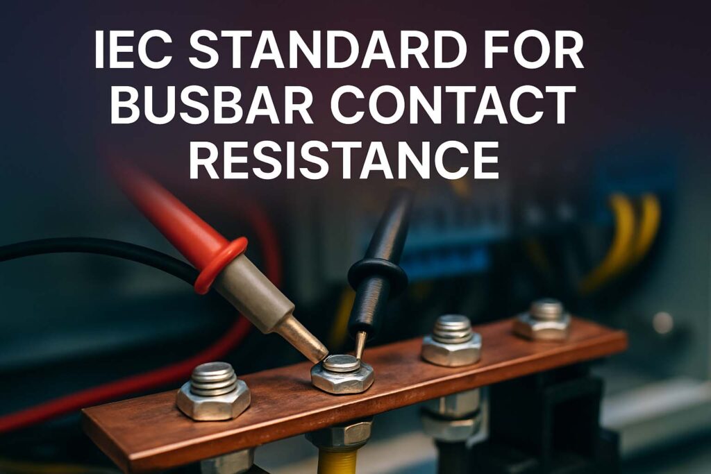
Contact resistance is measured using the micro-ohmmeter or ductor test, which follows a four-wire Kelvin connection method to eliminate lead and contact resistance of the measuring device.
Know more about IEC Standard for Cable Lugs
Steps Involved:
- Clean the contact area thoroughly
- Apply test current (typically 100A or higher)
- Measure voltage drop across the joint
- Calculate resistance using R = V / I
For repeatability, measurements should be done under the same torque and environmental conditions.
Maintenance and Periodic Testing
IEC 61439 encourages periodic verification of temperature rise and joint integrity. In practice, thermal imaging and ductor testing are used together to assess the health of busbar connections.
Poor contact resistance is one of the major causes of electrical panel failure. So, testing at intervals aligned with the system’s criticality is essential.
Busbar Contact Resistance in Solar and Industrial Systems
With the rise in solar energy installations and large-scale industrial electrification, the use of modular low-voltage panels has surged. These systems depend heavily on reliable busbar joints. High current loads and harsh environmental conditions make it even more important to comply with the IEC standard for busbar contact resistance.
System designers and panel manufacturers must ensure that every connection point is optimized for minimal resistance to reduce power loss and improve long-term reliability.
Real-World Implications of Non-Compliance
Failure to meet IEC standards for contact resistance can lead to:
- Equipment overheating
- Loss of efficiency
- Insulation damage
- Arc faults or electrical fires
- Voided warranties and regulatory penalties
By adhering to the IEC standard for busbar contact resistance, organizations can ensure their power systems are safe, compliant, and energy-efficient.
Know more about IEC Standard for Cable Tray
Final Thoughts on IEC Standard for Busbar Contact Resistance
The IEC standard for busbar contact resistance is a critical benchmark in modern electrical design. It protects systems from failure and improves energy efficiency by setting guidelines for testing, design, and maintenance of busbar joints. Though often overlooked, busbar contact resistance has a direct impact on operational safety and cost-effectiveness of electrical systems.
Follow Us on Social:
Subscribe our Newsletter on Electrical Insights for latest updates from Electrical Engineering Hub
#BusbarContactResistance, #IECStandard, #ElectricalStandards, #PowerDistribution, #SwitchgearDesign, #ElectricalTesting, #LowResistanceMeasurement, #BusbarTesting, #ElectricalEngineering, #SubstationDesign, #IEC60947, #ElectricalCompliance, #PanelBoardDesign, #ContactResistanceTest, #ElectricalSafety


