555 Timer IC Pins Configuration, Types, Modes and Applications
Table of Contents
Introduction
The 555 timer IC, also known as the NE555, is a highly versatile integrated circuit. That can be used in a variety of electronic applications. It was first introduced by Signetics in 1972. And has since become one of the most popular and widely used ICs in the electronics industry.
At its core, the 555 timer is a simple yet powerful timing device. That can be used to generate precise pulses of varying durations. It consists of a few basic components, including a pair of comparators, a flip-flop, and a discharge transistor. All of which are interconnected in a specific way to create a multivibrator circuit.
The 555 timer is used in a wide range of applications. Which includes oscillator circuits, pulse generators, LED flashers, and timer circuits. Its popularity and importance in the electronics industry can be attributed to its ease of use, versatility, and low cost.
Working of 555 Timer
The 555 timer operates by charging and discharging a capacitor through a series of internal components. At its most basic level, the circuit consists of two comparators, a flip-flop, and a discharge transistor. All of which are connected in a specific way to create a multivibrator circuit.
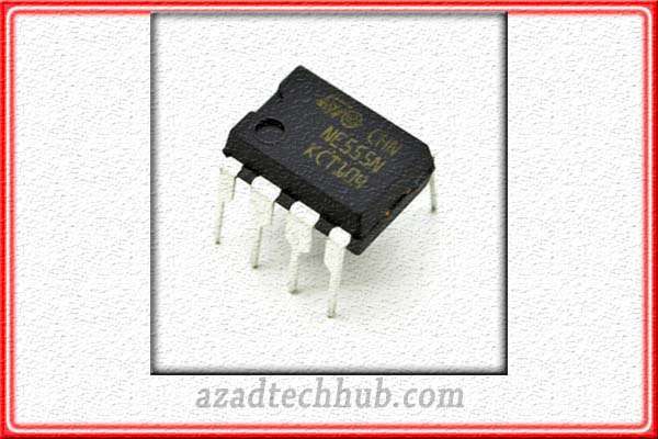
When power is applied to the 555 timer, the capacitor starts to charge through a resistor. Which is connected to the power supply. Once the voltage across the capacitor reaches a certain threshold. The first comparator triggers the flip-flop, which in turn activates the discharge transistor. This causes the capacitor to rapidly discharge, resetting the circuit and starting the cycle over again.
The 555 timer has three main modes of operation: monostable, astable, and bistable. In monostable mode, the circuit generates a single output pulse of a predetermined duration when triggered. While in astable mode, the circuit generates a continuous stream of pulses at a fixed frequency and duty cycle. In bistable mode, the circuit acts as a flip-flop, switching between two stable states based on the inputs to the circuit.
Few Examples of 555 Timer Circuits
The 555 timer has a wide range of applications in the electronics industry. From simple LED flashers to complex timing circuits. One common application is as a pulse generator. Where the circuit is used to generate precise pulses of a specific duration.
This can be useful in applications such as motor control, where the pulse width determines the speed of the motor. Another common application is as an oscillator circuit. Where the 555 timer is used to generate a continuous stream of pulses at a fixed frequency and duty cycle. This can be useful in applications such as tone generators or clock circuits.
The 555 timer can also be used in conjunction with other components to create more complex circuits. For example, it can be used as a voltage-controlled oscillator by varying the voltage across the timing capacitor.
It can also be used to create a PWM (pulse-width modulation) circuit. By just varying the duty cycle of the output pulses. 555 timer is a highly versatile and widely used IC that has become an essential component in the electronics industry. Its ease of use, versatility, and low cost make it a popular choice for a wide range of applications, from simple LED flashers to complex timing circuits.
Pins Configuration of 555 Timer IC
The 555 timer IC is a widely used and highly versatile integrated circuit that can be used in a variety of electronic applications. To understand how it works, it’s important to understand its internal structure and the function of each pin.
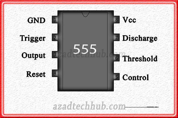
The 555 timer IC consists of 8 pins, each of which serves a specific function. Pin 1 is the ground pin, which is connected to the negative terminal of the power supply. The Pin 2 is the trigger pin, which is used to trigger the circuit and start the timing cycle.
Then Pin 3 is the output pin, which provides the output signal generated by the circuit. Pin 4 is the reset pin, which is used to reset the timing cycle and start a new one.
The Pin 5 is the control voltage pin, which is used to adjust the timing interval. Pin 6 is the threshold pin, which sets the voltage level at which the timing cycle ends. The Pin 7 is the discharge pin, which discharges the timing capacitor. Pin 8 is the power supply pin, which is connected to the positive terminal of the power supply.
Internal Structure of 555 Timer IC
The internal structure of the 555 timer IC consists of three main components: two comparators, a flip-flop, and a discharge transistor. These components are interconnected in a specific way to create a multivibrator circuit that generates precise pulses of varying durations.
The VCC and GND pins are connected to the power supply, and the other pins are connected to external components to create the desired circuit. The trigger and threshold pins are connected to a voltage divider circuit consisting of two resistors and a timing capacitor. The output pin is connected to an external load, such as an LED or a motor.
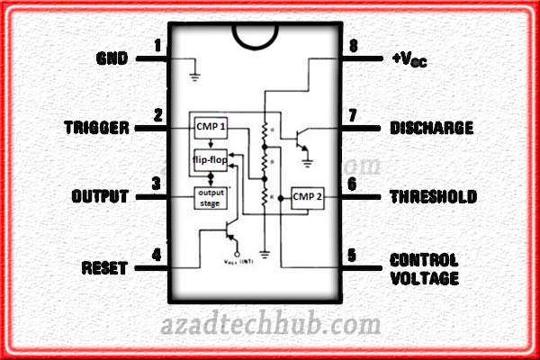
When power is applied to the 555 timer IC, the timing capacitor starts to charge through the voltage divider circuit. Once the voltage across the capacitor reaches a certain threshold, the first comparator triggers the flip-flop, which in turn activates the discharge transistor. This causes the capacitor to rapidly discharge, resetting the circuit and starting the cycle over again.
Types of 555 Timer IC
There are different types of 555 timer ICs available in the market, each designed for specific applications. Here are some of the most common types:
NE555
This is the most popular and widely used type of 555 timer IC. It has a wide range of applications in various electronic circuits, such as oscillators, timers, and PWM (pulse-width modulation) controllers. NE555 is a bipolar device that can operate on a wide range of voltages, making it suitable for both low and high voltage applications.
LM555
This is a CMOS version of the 555 timer IC, which is designed to have lower power consumption and higher input impedance compared to the NE555. LM555 is ideal for battery-operated applications and can operate on a voltage range of 2V to 18V. It is commonly used in circuits such as LED flashers, tone generators, and PWM controllers.
TLC555
This is a low-power CMOS version of the 555 timer IC that is designed to operate on low voltage and low power consumption applications. It has a wide voltage range of 2V to 15V and is commonly used in circuits such as power management, motor control, and temperature sensors.
LMC555
This is a precision CMOS version of the 555 timer IC, which is designed to have low drift and high accuracy. LMC555 is commonly used in applications such as precision timing, frequency generators, and PLL (phase-locked loop) circuits.
ICM7555
This is a low-power, high-performance CMOS version of the 555 timer IC, which is designed for precision timing and oscillation applications. It has a wide voltage range of 2V to 18V and is commonly used in circuits such as precision timing, frequency generators, and voltage-controlled oscillators.
Each type of 555 timer IC has its own specific characteristics and applications. For instance, NE555 is suitable for both low and high voltage applications, while LM555 is ideal for low-power and battery-operated applications. TLC555 is designed for low voltage and low power consumption applications, while LMC555 is ideal for precision timing and frequency generators. ICM7555 is a high-performance version of the 555 timer IC, designed for precision timing and oscillation applications.
Choosing the right type of 555 timer IC for a specific application is crucial to achieve optimal performance and efficiency. Understanding the specific characteristics and applications of each type can help in selecting the appropriate one for a particular circuit.
Modes of Operation of 555 Timer IC
The 555 timer IC can operate in three different modes: Monostable, Astable, and Bistable. Each mode has a unique configuration and application.
a) Monostable Mode: In this mode, the 555 timer IC generates a single pulse of a fixed duration when triggered. The pulse duration can be adjusted using external components. The output of the timer remains low until triggered, and then goes high for the duration of the pulse.
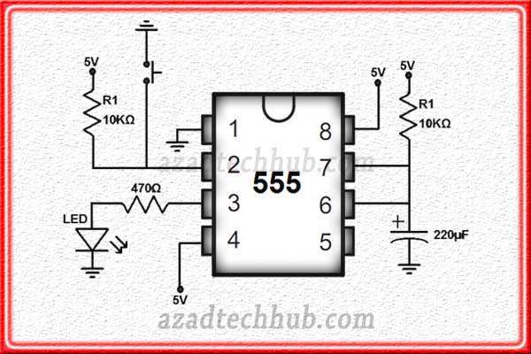
Applications include One-shot pulse generators, Timing circuits, Delay circuits and Frequency dividers
b) Astable Mode: In this mode, the 555 timer IC generates a continuous square wave output with a fixed frequency and duty cycle. The frequency and duty cycle can be adjusted using external components.
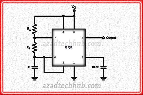
Applications include Oscillators, Clock generators, Tone generators, LED flashers, PWM (Pulse-Width Modulation) controllers
c) Bistable Mode: In this mode, the 555 timer IC functions as a flip-flop, toggling between two stable states with each trigger input. The output of the timer remains in one of two states until the next trigger input is received.
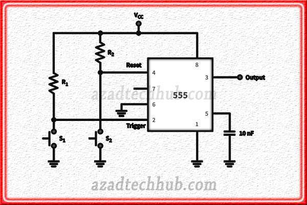
Applications include Flip-flops, Control circuits, Traffic lights and Touch switches.
Five Projects using 555 Timer IC
Here are five fun and simple DIY projects using the 555 timer IC:
Blinking LED Circuit
Parts list include 555 timer IC, 2 LEDs, 2 220 ohm resistors, 10k ohm resistor, 2 electrolytic capacitors (10 uF and 100 uF), breadboard, jumper wires, battery, and battery clip.
Now, connect pin 2 of the 555 timer IC to the positive rail of the breadboard and pin 1 to the negative rail. Then Connect the 10k ohm resistor between pins 6 and 7, and the 100 uF capacitor between pin 2 and 6. Connect the 220 ohm resistor to pin 3 of the IC, and the LED to the resistor. Repeat for the other LED. Then connect the 10 uF capacitor between pin 5 and the negative rail. At the end connect the battery and clip to the rails.
Siren Circuit
Parts list include 555 timer IC, speaker, 470 ohm resistor, 10k ohm resistor, 1k ohm resistor, 100k ohm resistor, 0.1 uF capacitor, 1 uF capacitor, 2.2 uF capacitor, 9V battery, and battery clip.
At start connect pin 2 of the 555 timer IC to the positive rail of the breadboard and pin 1 to the negative rail. Then connect the 470 ohm resistor between pin 3 and the speaker.
Connect the 10k ohm resistor between pins 6 and 2, and the 1k ohm resistor between pins 6 and 7. Then connect the 100k ohm resistor between pin 7 and the negative rail, and the 0.1 uF capacitor between pin 5 and the negative rail. Connect the 1 uF capacitor between pins 2 and 1, and the 2.2 uF capacitor between pins 6 and 2. At the end connect the battery and clip to the rails.
Astable Multivibrator Circuit
Parts list include 555 timer IC, 2 10k ohm resistors, 1 100k ohm resistor, 2 10 uF capacitors, breadboard, jumper wires, and LEDs.
At the start connect pin 2 of the 555 timer IC to the positive rail of the breadboard and pin 1 to the negative rail. Then connect the 100k ohm resistor between pins 6 and 7, and the 10 uF capacitor between pin 2 and 6. Connect the 10k ohm resistors to pins 6 and 2, and connect an LED to each resistor. Then connect the 10 uF capacitor between pin 5 and the negative rail. At the end connect the battery and clip to the rails.
PWM LED Dimmer Circuit
Parts list include 555 timer IC, NPN transistor, 2 10k ohm resistors, 1k ohm resistor, 10 uF capacitor, breadboard, jumper wires, LED, and potentiometer.
At the start, connect pin 2 of the 555 timer IC to the positive rail of the breadboard and pin 1 to the negative rail. Connect the 1k ohm resistor to pin 3 of the IC, and the transistor to the resistor. Then connect the 10k ohm resistor between pins 6 and 2, and the potentiometer to pins 6 and 7. Connect the 10 uF capacitor between pin 5 and the negative rail. Then connect the LED to the transistor. At the end connect the battery and clip to the rails.
PWM LED Dimmer Circuit
Parts List include 555 Timer IC,10kΩ Resistor,100kΩ Resistor,0.1µF Capacitor,10µF Capacitor, LED, Transistor (BC547 or equivalent),9V Battery, Breadboard, Jumper Wires, Aluminum foil or copper tape, A small piece of cardboard or plastic for touch sensor pad.
Place the 555 timer IC on the breadboard. The pins of the IC should be placed in the correct positions.
Which can be found on the datasheet for the IC. Connect a 10kΩ resistor between pins 6 and 7 of the IC, connect a 100kΩ resistor between pins 6 and 2 of the IC, connect a 0.1µF capacitor between pins 5 and 2 of the IC, connect a 10µF capacitor between pins 1 and 2 of the IC.
Connect the anode of the LED to pin 3 of the IC and the cathode to ground, connect the base of the transistor to pin 3 of the IC, the collector to the positive rail, and the emitter to the negative rail, Connect a jumper wire from the positive rail to pin 8 of the IC, Connect a jumper wire from the negative rail to pin 1 of the IC.
Create a touch sensor pad by cutting a small piece of cardboard or plastic and covering it with aluminum foil or copper tape. Connect one end of a jumper wire to the foil or tape and the other end to pin 2 of the IC, connect another jumper wire from pin 4 of the IC to the touch sensor pad and connect a 9V battery to the breadboard to power the circuit.
Conclusion
In conclusion, the 555 timer IC is an essential component in electronics. Widely used in a variety of applications due to its simplicity, versatility, and reliability. We have discussed the internal working of the IC. Its various modes of operation, and how to build some DIY projects using the IC.
We have also highlighted some common issues and troubleshooting tips to help you overcome any problems that may arise. It is worth noting that the 555 timer IC is not limited to the projects we have discussed. There are numerous other applications that you can explore. And with a little creativity and ingenuity, you can create unique and useful circuits that meet your specific needs.
If you’re interested in learning more about the 555 timer IC, there are plenty of online resources, tutorials, and datasheets available. You can also consider investing in a beginner’s electronics kit that includes a 555 timer IC to get some hands-on experience. The 555 timer IC is a powerful tool in the world of electronics, and with a little bit of experimentation and creativity, you can leverage its full potential to create exciting and innovative projects.
Follow us on LinkedIn”Electrical Insights” to get the latest updates in Electrical Engineering. You can also Follow us LinkedIn to see our latest posts.


