IEC Standard for Busbar Clearance
Understanding the IEC Standard for Busbar Clearance
The IEC standard for busbar clearance plays a critical role in the design and safety of electrical panels and power distribution systems. It defines the minimum distances between live parts and between live parts and earthed metal parts. These clearances help prevent arcing, short circuits, and accidental electric shock.
Busbars carry large amounts of current and are used in switchgear, transformers, and distribution boards. Due to the high energy involved, ensuring the right physical spacing between these conductors is crucial.
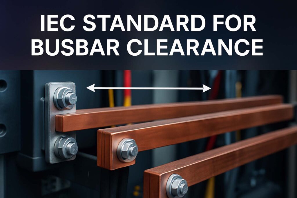
The International Electrotechnical Commission (IEC) provides globally accepted guidelines for busbar clearances. These standards help engineers design systems that are safe, reliable, and compliant with international codes.
Why Busbar Clearance Matters
In any electrical system, safety is a top priority. Busbars are usually made of copper or aluminum, and they carry high current. When the clearance is not maintained properly, several issues can arise:
- Flashover between phases or between phase and earth
- Equipment failure due to insulation breakdown
- Fire hazards from arc faults
- Safety risks to maintenance personnel
Proper busbar clearance prevents these hazards and improves the system’s longevity. That is why following the IEC standard for busbar clearance is not optional—it is a necessity.
Key Parameters Defined in IEC Standard for Busbar Clearance
The IEC provides specific guidelines on electrical clearances. Two terms are important here:
- Clearance – The shortest distance in air between two conductive parts
- Creepage distance – The shortest distance along the surface of the insulating material between two conductive parts
These distances are influenced by voltage level, pollution degree, and the system insulation category.
The IEC 61439-1 standard is the most commonly used document for defining these values. It applies to low-voltage switchgear and control gear assemblies and provides a table of minimum clearances.
Know more about IEC Standard for Cable Tray
Minimum Clearances as per IEC 61439-1
Here’s a summarized table for minimum air clearance based on rated impulse withstand voltage:
| Rated Impulse Withstand Voltage (kV) | System Voltage (V) | Minimum Clearance (mm) |
|---|---|---|
| 1.5 | Up to 300 | 1.5 |
| 2.5 | 300 – 600 | 3.0 |
| 4.0 | 601 – 1000 | 5.5 |
| 6.0 | 1001 – 1200 | 8.0 |
| 8.0 | 1201 – 1500 | 11.0 |
These values are the absolute minimum. Many engineers apply an extra safety margin, especially in dusty or humid environments.
Know more about IEC Standard for Battery Energy Storage System
Pollution Degree and Its Effect on Busbar Clearance
IEC classifies environments based on pollution degree, which impacts insulation and clearance requirements:
- Pollution Degree 1: No pollution or only dry, non-conductive pollution
- Pollution Degree 2: Normally non-conductive, but can become conductive due to condensation
- Pollution Degree 3: Conductive pollution or dry pollution that becomes conductive
- Pollution Degree 4: Persistent conductive pollution, e.g., outdoor installations
Higher pollution degrees require larger creepage distances. Even when clearance is sufficient, inadequate creepage can cause tracking or surface discharge.
In pollution degree 3, designers must use bigger phase-to-phase and phase-to-earth spacing, or use additional insulation barriers.
Common Clearances in LV and MV Busbar Systems
While IEC provides guidelines, typical values used in practice are often more conservative.
Typical Phase-to-Phase and Phase-to-Earth Clearances
| System Voltage | Busbar Type | Phase-to-Phase (mm) | Phase-to-Earth (mm) |
|---|---|---|---|
| 415V AC | Copper | 25 – 30 | 20 – 25 |
| 660V AC | Copper | 35 – 40 | 30 – 35 |
| 11kV | Air Insulated | 180 – 210 | 150 – 180 |
These are practical values, often higher than the IEC minimums, and depend on system design, enclosure size, and environmental conditions.
Know more about IEC Standard for Busbar Sizing
Impact of Altitude on Busbar Clearance
IEC also highlights the influence of installation altitude. At elevations above 2000 meters, air pressure drops, reducing the dielectric strength of air.
To maintain insulation performance, clearance values must be increased. For instance, at 3000 meters, the clearance should be increased by approximately 25%.
For accurate calculation, engineers use correction factors or refer to IEC 60664-1, which gives detailed altitude adjustment charts.
Clearance Requirements for Insulated vs. Bare Busbars
There is a significant difference between bare busbars and insulated busbars. Insulated busbars can use smaller clearances because the insulation prevents arcing.
However, designers should ensure that insulation is tested for thermal, mechanical, and electrical stress over time. For busbars covered with heat shrink or epoxy coating, minimum clearances may be based on the insulation’s performance rather than air distance.
That said, bare busbars require larger clearances, and any foreign object entering the panel can cause immediate failure. This is why maintenance panels with bare conductors must be designed with safe working distances.
Installation and Mounting Guidelines
Proper mounting supports the busbar and maintains clearance. The spacing of busbar supports affects mechanical strength during short circuits. Supports must not allow sagging or vibration that could reduce the gap between phases.
Some IEC-based good practices include:
- Using non-conductive support insulators
- Ensuring uniform phase spacing
- Avoiding sharp bends or overlaps
- Placing barriers or shrouds for added protection
Know more about IEC Standard for Air Circuit Breaker
Design Tips for Meeting IEC Busbar Clearance Standards
To ensure your panel design meets the IEC standard for busbar clearance, consider the following tips:
- Choose proper busbar profile and layout to avoid tight spacing
- Use vertical or horizontal segregation if necessary
- Always verify clearances during panel assembly with feeler gauges or templates
- Consider arc barriers to increase fault containment
- Factor in cable entries and terminal points that could affect spacing
Engineers should also account for thermal expansion. As temperature increases, metal expands, and this could reduce the spacing between busbars over time.
Common Mistakes in Busbar Clearance Design
Despite guidelines, several errors still occur in practice:
- Misinterpreting voltage classes (e.g., using 415V clearance for 660V systems)
- Ignoring environmental factors like humidity or pollution
- Using outdated standards or unclear manufacturer datasheets
- Not verifying post-installation busbar positioning
- Skipping altitude correction for high-elevation installations
These mistakes can cause catastrophic failure, so design review and quality control are essential.
Know more about IEC Standard for Cable Lugs
Conclusion: Adhering to IEC Standard for Busbar Clearance
The IEC standard for busbar clearance provides a reliable framework for designing safe and efficient electrical systems. Following this standard protects equipment and personnel from dangerous faults and prolongs system life.
It is not just about meeting minimum numbers; the goal is to ensure long-term safety under real-world conditions. By understanding the factors involved—voltage levels, pollution degrees, altitude, insulation type, and busbar arrangement—engineers can design robust panels that meet international safety expectations.
Follow Us on Social:
Subscribe our Newsletter on Electrical Insights for latest updates from Electrical Engineering Hub
#IECStandard, #BusbarClearance, #ElectricalSafety, #PowerDistribution, #SwitchgearDesign, #BusbarStandards, #IEC61439, #ElectricalEngineering, #BusbarInstallation, #SubstationDesign, #ClearanceRequirements, #BusbarSpacing, #ElectricalCodeCompliance, #LowVoltageSwitchgear, #PanelBoardDesign



I saw a lot of website but I conceive this one has got something extra in it in it