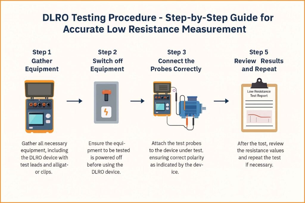
DLRO Testing Procedure – Step-by-Step Guide for Accurate Low Resistance Measurement
When it comes to electrical testing, precision matters. One of the most important tests for ensuring the reliability of electrical equipment is DLRO testing, or Digital Low Resistance Ohmmeter testing. It helps detect issues like poor joints, loose connections, or damaged conductors in switchgear, transformers, cables, and busbars. In simple terms, DLRO testing procedure determines the resistance of electrical connections that should ideally be close to zero.
Table of Contents
Table of Contents

Understanding how to perform a DLRO test properly is crucial for engineers, maintenance technicians, and electrical professionals who want to maintain system efficiency and prevent overheating or energy loss. This guide will walk you through the DLRO testing procedure, explaining each step in detail, along with precautions, typical readings, and tips for accurate results.
Before jumping into the testing process, it’s essential to understand the principle behind DLRO testing and why it is widely used in electrical maintenance programs.
Key Takeaways
- DLRO Testing Procedure ensures the integrity of low-resistance joints and conductors.
- It helps identify loose or corroded connections that can cause overheating or equipment failure.
- The test uses a high current (up to 100A) and measures the resulting voltage drop to calculate resistance using Ohm’s Law.
- Proper connections, polarity, and contact pressure are critical for accurate results.
- It’s a non-destructive and quick test that provides essential data for preventive maintenance.
What is DLRO Testing?
DLRO stands for Digital Low Resistance Ohmmeter. It is a precision instrument that measures very low resistances, typically from 0.1 µΩ to 2000 Ω, depending on the model. The test works on Ohm’s Law (R = V/I) ; the meter applies a known current through the test object and measures the voltage drop across it.
This type of testing is used to verify the quality of electrical connections in high-current paths such as:
- Transformer windings
- Busbar joints
- Circuit breaker contacts
- Cable terminations
- Motor windings
Since high resistance in these parts can lead to power loss and heat generation, regular DLRO testing is essential for safety and efficiency.
Know more about Contact Resistance Test IEC Standard: Best Guide for Accurate Electrical Testing
Why DLRO Testing Procedure is Important
A well-executed DLRO testing procedure ensures the reliability and performance of electrical systems. Even a small resistance at a joint can lead to a large voltage drop when carrying high current. This can cause:
- Overheating of conductors
- Voltage imbalance
- Power losses
- Accelerated insulation degradation
- Potential fire hazards
Therefore, DLRO testing is a vital part of predictive maintenance and commissioning tests in power plants, substations, and industrial facilities.
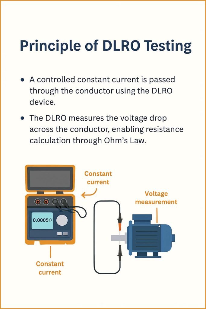
Principle of DLRO Testing
The principle of DLRO testing is simple yet highly effective. The tester injects a stable DC current through the test object and measures the voltage across it. The device then calculates resistance using the formula:
R = V / I
Where:
- R = Resistance (in ohms)
- V = Voltage drop (in volts)
- I = Current (in amperes)

To eliminate errors due to lead resistance, the DLRO uses a four-terminal (Kelvin) connection method — two terminals for current injection and two for voltage measurement.
Know more about IEC Standard for Cable High Voltage Test: Best Guide
Instruments Used in DLRO Testing Procedure
The following equipment is commonly used while performing a DLRO test:
| Equipment Name | Function |
|---|---|
| Digital Low Resistance Ohmmeter | Main device to measure low resistance |
| Test Leads (Kelvin Type) | Ensure accurate current and voltage connection |
| Power Source (Internal or External) | Supplies DC current for measurement |
| Cleaning Materials | Used for cleaning contact surfaces |
| Personal Protective Equipment (PPE) | Safety gloves, goggles, and insulated shoes |
DLRO Testing Procedure – Step by Step
Now, let’s go through the DLRO testing procedure step-by-step. Follow these instructions carefully to ensure accurate and safe testing.
Step 1: Preparation and Safety Check
- Verify that the test area is de-energized and properly isolated.
- Ensure you have a work permit and follow all site safety regulations.
- Use appropriate PPE (Personal Protective Equipment).
- Clean the test points to remove dirt, oil, or corrosion.
Step 2: Instrument Setup
- Turn on the DLRO tester and check its calibration date.
- Select the correct current range based on the test object. Typically, 10A to 100A DC is used.
- Connect the four terminals properly (two for current and two for potential).
Step 3: Making Connections
- Connect the C1 and C2 leads to inject the current through the object under test.
- Connect the P1 and P2 leads across the same points to measure voltage drop.
- Ensure tight and clean connections to avoid contact resistance errors.
Step 4: Perform the Test
- Initiate the test by pressing the “Test” or “Start” button.
- The DLRO will pass current through the circuit and display resistance on the screen.
- Take multiple readings for accuracy and consistency.
Step 5: Record the Results
- Record the measured resistance in a test log sheet.
- Compare readings with manufacturer recommendations or baseline data.
- Typical acceptable resistance for busbar joints or cable connections is less than 100 µΩ.
Know more about High Voltage Transformer Testing Procedure
Step 6: Analyze and Interpret
If the resistance value is higher than expected, it could indicate:
- Poor contact or loose joint
- Oxidation or corrosion
- Damaged conductor strands
In such cases, retighten or clean the connection and repeat the test to confirm improvements.
Typical DLRO Test Results Table
| Equipment Type | Acceptable Resistance (µΩ) | Remarks |
|---|---|---|
| Transformer winding | 200 – 400 | Should be balanced across phases |
| Busbar joint | <100 | Indicates good connection |
| Circuit breaker contact | <150 | Higher values may suggest pitting |
| Cable termination | <200 | Must be consistent for all phases |
Precautions During DLRO Testing Procedure
Performing a DLRO testing procedure requires careful attention to detail. Follow these safety and operational precautions:
- Never perform the test on energized equipment.
- Ensure proper polarity of test leads.
- Use short and thick cables to minimize lead resistance.
- Avoid inductive components (like large coils) unless the instrument supports it.
- Always discharge the circuit after testing to remove stored charge.
Factors Affecting DLRO Test Results
Several factors can influence the accuracy of readings during the DLRO testing procedure:
| Factor | Impact |
|---|---|
| Contact resistance | Can lead to higher readings |
| Temperature variations | Resistance increases with temperature |
| Lead wire length | Longer leads add unwanted resistance |
| Dirty terminals | Poor contact affects voltage drop |
| Magnetization (in inductive loads) | Causes unstable readings |
Maintaining consistent testing conditions and using high-quality equipment helps minimize these errors.
Know more about IEC Standard for DC Cable Sizing – Complete Technical Guide
Applications of DLRO Testing
DLRO testing is used across a wide range of electrical and industrial applications, including:
- Power transformers (to check winding resistance)
- Circuit breakers (contact resistance testing)
- Large motors and generators
- Transmission line joints and busbars
- Substation commissioning and maintenance
Its ability to detect minute resistance differences makes it a powerful diagnostic tool for preventive maintenance.
Advantages of DLRO Testing Procedure
Performing the DLRO test offers several advantages:
- Accurate and fast results even at micro-ohm levels
- Non-destructive testing method
- Helps in detecting hidden connection issues early
- Portable and easy-to-use instruments
- Improves equipment reliability and performance
Know more about IEC Standard for DGA Analysis – Complete Technical Guide
DLRO Testing Procedure Example
Suppose you are testing the busbar connection in a 11kV panel. You apply a test current of 100A and the instrument displays a voltage drop of 5mV.
Using Ohm’s Law:
R = V/I = 0.005 / 100 = 50 µΩ
This indicates the connection is in good condition since the resistance is within acceptable limits.
Troubleshooting Common Issues
If you observe inconsistent or abnormally high readings, consider these corrective steps:
- Check and re-tighten all test lead connections.
- Clean contact surfaces.
- Verify instrument calibration.
- Repeat the test using a different current range.
- Ensure the test object is not inductive or connected to other circuits.
Final Thoughts on DLRO Testing Procedure
The DLRO testing procedure is one of the most reliable and essential tests in the field of electrical maintenance. It provides valuable insight into the integrity of current-carrying paths, helping prevent potential failures and improving overall system performance.
By following the correct testing steps, maintaining proper safety measures, and interpreting results carefully, engineers can ensure long-term reliability and efficiency of electrical installations. Regular DLRO testing not only supports preventive maintenance but also enhances operational safety in industrial environments.
Know more about IEC Standard for Battery Charger – Complete Technical Guide
In summary, understanding and correctly applying the DLRO testing procedure is key to maintaining a healthy electrical system. With proper care and accurate testing, you can detect faults before they cause costly downtime or equipment damage.
Follow Us on Social:
Subscribe our Newsletter on Electrical Insights for latest updates from Electrical Engineering Hub
#DLROTestingProcedure, #LowResistanceMeasurement, #ContactResistanceTest, #ElectricalTesting, #TransformerMaintenance, #CircuitBreakerTesting, #OhmicTesting, #MicroOhmMeter, #ElectricalEngineering, #PowerSystemTesting, #PreventiveMaintenance, #TestAndMeasurement, #SubstationTesting, #RelayTesting, #ElectricalInspection


